During early prototype testing of the Javelin it became
apparent that the engine was mechanically noisy in a harsh resonating manner.
This was deemed to be a major problem given that the Javelin was to be a luxury
small family car and as such a remedy was required. Two types of crankcase had
been manufactured, one in cast-iron, the other in aluminium. Experimental
testing on these early designs made it clear that there was considerable whirl
of the crankshaft and a certain amount of flexing on the crankcase was evident
from edge marking on the bearings.
The next stage of development was to manufacture a cast-iron
crankcase and a three bearing crankshaft, the bearing-cap joint faces now being
horizontal, so the crankshaft could be dropped out of the bottom of the engine.
The first engine tested of this type was a 1200cc unit, but when experiments
were carried out with larger diameter liners, increasing the capacity to
1500cc, considerable crankcase ‘thump’ was experienced. To overcome this for
testing purposes a boiler plate was bolted across the bottom of the
bearing-caps, however this only highlighted the inherent weakness of this
crankcase design. Subsequent development led to the adoption of light-alloy
crankcases split vertically, which permitted the use of tie-bolts, making the
whole assembly much stiffer.
 |
| Alloy crankcase of the production Jowett flat-four |
Jowett had noted that cast-iron crankcases resulted in a
quieter engine, but it was decided that the alloy crankcase should be proceeded
with as it had been designed for die-casting. The cast-iron version was
approximately 10% quieter than the alloy one, but was naturally heavier. In
view of this and the difficulty at that time of obtaining iron castings, the
spilt alloy crankcase was decided upon. It was also at this stage that the 1200cc
project was dropped, as there was a large performance difference between it and
the 1500cc engine.
When the revised engine was power tested, a considerable
drop in performance was seen above 4250rpm. This was attributed to inadequate
breathing and poor turbulence in the stepped head. The valve lift was increased
from 0.275in to 0.315in and the ports ‘cleaned up’. Weslake was called in to
inspect the combustion chamber and he evolved a semi-pancake head with 14mm
plugs easier to produce and increasing top-end power by 15%, while providing
smoother running. The exhaust system was changed from streamlined exhaust ports
brought out to the bottom face of the head, to a manifold bolted to the
underside of the head, the off-side manifold feeding into a pipe running round
the front of the engine to enter the near-side manifold and take benefit
thereby of extractor action. The main exhaust pipe led from the back of the
near-side manifold. It had 1 3/8in inside diameter and the power drop with
silencers was only 3 BHP compared with an open pipe. This new exhaust
arrangement gave a power increase of 1.5% and resulted in the cylinder heads no
longer being handed, a production and servicing advantage.
 |
| Jowett engine sectioned |
Snatchy running below 20mph lead to an increase of flywheel
diameter to the limits of the bell-housing. Another alteration required
following testing, was to change the main bearing clearance due to rapid
crankcase expansion. A steel housing giving 0.0003in to 0.0018in clearance at
assembly temperature was adopted.
The Javelin emerged as the first really new British post-war
car. It was a comfortable, brisk 5/6 seater saloon giving 75/80 mph and 28/32
mpg with advanced aspects such as the flat four engine, torsion-bar suspension
and wind-defeating body form
The prototype engines, developing 40-45 BHP had been
satisfactory in respect of bearings, but long-distance driving on the Continent
with the early production versions showed up a tendency to run big-end and main
bearings.
With the previously mentioned improved breathing 50-52 BHP
was developed at 4500rpm, and it was decided that white-metal bearings must be
replaced by copper-lead bearings, if possible in conjunction with the existing
EN 12 steel crankshaft. The flat-four layout led to higher oil temperatures
than are experienced in in-line designs, which contributed to the bearing
failures.

Initially sintered copper-lead bearings with a white metal
flash of 0.00125in were utilised with the un-hardened steel crankshaft. These
bearings showed no signs of fatigue, but were extremely sensitive to dirt and
scuffing on the crankshaft. A hardened crankshaft was therefore adopted with
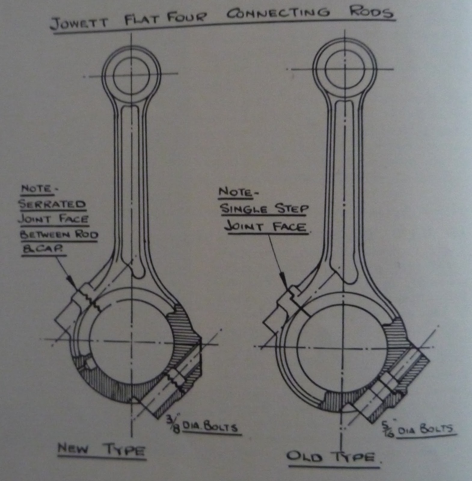
special care being paid to assembly and running-in. It was also found that the
stepped location on the big-end led to distortion on tightening, so a new
con-rod was devised, the big-end having an offset serrated face and clamp bolts
increased to 0.375in and 400lb/in tightening torque. A dirt trap hole of 1/16in
diameter had a negligible effect on oil pressure and consumption. The
crankshaft was induction hardened on the journals and pins to a hardness of
512-530 Brinell, and the bearing surfaces were lapped to a finish of 8-12
micro-inches against the former 12-24 micro-inches. A softer bearing material
of 30% lead, 1.2% tin and 68.8% copper with a 0.00025 in plated white-metal
layer for running-in was used with the new rods and crankshaft and the bearings
now stood up to 50 BHP and 4750 rpm in spite of the higher oil temperatures and
compact bearings of the flat-four layout.
The lubrication system was thoroughly tested in the initial
stages of development, an engine being rigged for measurement of oil spillage
from bearings, relief valve, ancillary services etc. As a result, the feed to
the main bearings was increased and the size of the oilways increased to 7/16in
diameter to obviate a possible danger of bearing starvation under cold-start
conditions with the full-flow filter system adopted to ensure clean oil for the
hydraulic tappets. The pressure relief valve exhausted beneath the sump oil
level to avoid aeration and later the discharge was by-passed to the pump
suction side, within the cover.
Initially the three-bearing crankshaft engine suffered with
oil swirl due to air transferring from one side of the crankcase to the other.
To prevent this, a surface baffle was fitted which allowed the free passage of
air only. Originally the oil pump had been mounted on a bearing cap, but the
vertically split cases obviated this location, so it was moved to the
timing-case wall and driven by spiral gears from the crankshaft. The distributor
was also repositioned to allow it to be mounted vertically and use a common
drive-shaft as the oil pump from the spiral bevel gear on the crankshaft. The
oil pump capacity was also increased which meant oil pressure rose from
50lb/sq.in to 65lb/sq.in. Following use on Jowett’s competition cars, an
oil-cooler built to Jowett’s specification was incorporated on production
engines in 1952. Initially this was placed rewards for accessibility, but later
was moved to a location between the fan and radiator. With the oil-cooler in
circuit, pressure pulsations occurred at audible frequencies until the
previously mentioned dirt-trap holes in the big-end caps were deleted.


In vehicle testing it was shown that louvers in the bonnet
became ineffective in terms of extracting air from behind the radiator above
50mph. Pressure areas were checked and it was found possible to take air from
behind the radiator via apertures in the front wheel arches.
An issue with early production engines was noisy valve gear,
even with the zero lash hydraulic tappets. Improved manufacturing tolerances
were introduced, but the noise was still deemed unacceptable. Jowett then went
on to investigate the effect of valve opening/closing ramp sizes and also
velocity profiles. After much experimentation Jowett settled on cams with a
0.008in opening ramp and 0.020in closing ramp (from the fierce initial 0.002in
and 0.006in ramps on the inlet and exhaust respectively). Unfortunately
hydraulic tappets became unobtainable during 1950 and the noise level rose
somewhat with the enforced use of conventional tappets.
Experiments were made with the material for camshafts and
tappets. Excellent results were found with a high duty 1% chromium cast iron
camshaft with a tip hardness of 40-45 Rockwell C and chilled iron tappets of a
similar hardness and a finish of 7-10 micro inches. A phosphate process on cam
and tappet faces to retain oil during running-in was found to be beneficial,
but not necessary.
Five different types of liner/piston combinations were used
in the course of development. Vacrit high-duty manganese chromium iron liners
with a 280-270 Brinell surface hardness were originally used, in conjunction
with split-skirt pistons in LO-EX or LM13 alloys withtwo D/26 radial thickness
pressure rings and a slotted oil-control ring.
A taper-faced Vacrome chromium-plated top piston ring was
adopted to cut oil consumption, without complete success. Liner distortion was
suspected and investigation showed that whilst 0.008-0.010in gasket nip at
38/40 lb/ft cylinder head tightening torque was satisfactory to retain gas and
water seals, this was highly critical; any degree of higher torque loading or
excessive nip caused local liner collapse and consequently distortion. To
counteract this, the liner section was stiffened and an internally-stepped
second ring fitted to facilitate quick bedding-in of the chromium-plated piston
ring. Following this a Javelin ran 80,000 miles in the course of testing by
Avon India Rubber Co. Ltd., gave an average of 3,700 mpg of oil at 37.39 mph
average speed, and maximum bore wear averaged 0.002in, equal to 40,000 miles
per thou.
Due to the Javelin’s unusual firing order of 1-3-2-4
carburation was paid special attention. Cylinder 1 and 3 are fed from one
carburettor via siamesed ports, and 2 and 4 from the other carburettor. To
prevent a weak mixture in the front two cylinders of each bank caused by inlet
tract surge, a 0.55in diameter balance pipe was added between the two
carburettors. Intake noise was a problem on the Javelin and Jowett went on
to test many different types of air filter and silencer, but no satisfactory solution
was found. Instead Jowett evolved their own baffle box which was located in the
alligator-bonnet, tuned to length to suit the induction system, and connected
to a resonance chamber which was coupled to the air intakes by vertical pipes
having squash rubber connections which broke as the bonnet was lifted. A non-spill
oil-bath air filter was incorporated.
In addition to the early bearing failures and excessive oil
consumption, gasket blowing was an issue on some Javelins. It was subsequently
found that this was due to a too small an asbestos content at the fold of the
gasket, however it was only with the increased output for competition purposes
that this cause was identified.